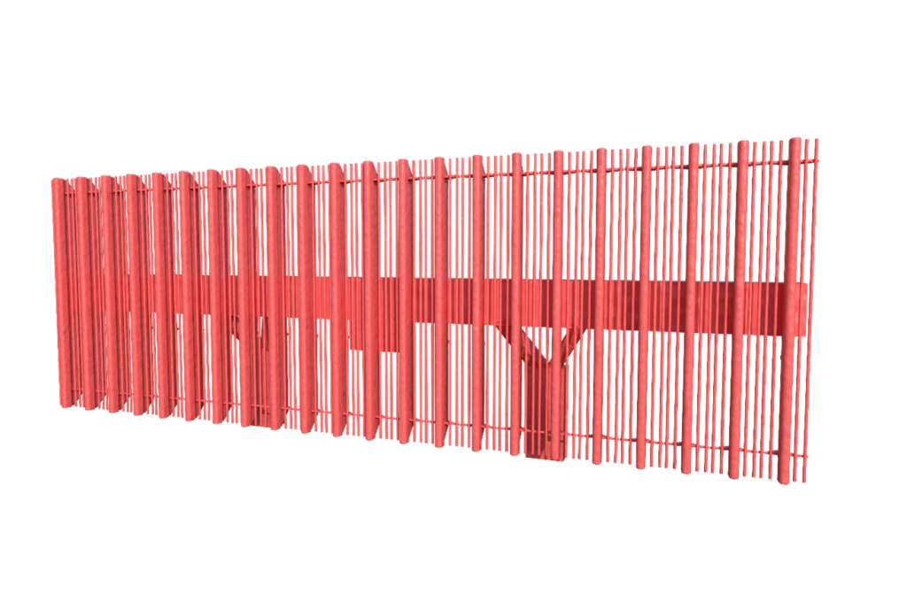
Secondary channel antenna
The secondary channel antenna of the airfield radar is designed to transmit interrogation signals at a frequency of 1030 MHz and receive response signals at a frequency of 1090 MHz. The secondary channel antenna is a planar antenna array, which consists of 20 vertical sector antennas. A sector antenna in the E-plane forms a radiation pattern of a special shape in the form of a cosecant. In request mode, the secondary channel antenna generates a total pattern with a main lobe width of H-plane equal to 3.4°. When receiving, the secondary channel antenna forms two diagrams: sum and difference. The width of the main lobe of the total radiation pattern at reception is 3.1 °.
CISPR 16-1-1 standard
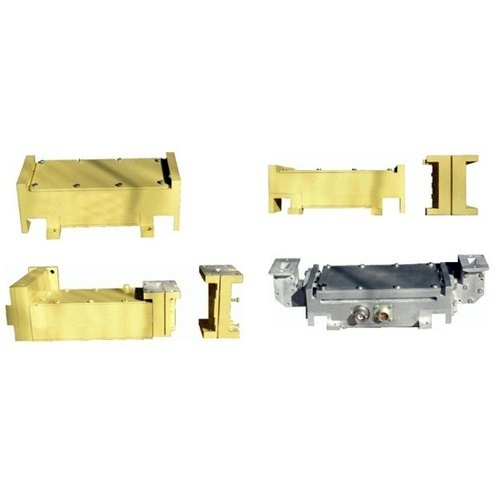
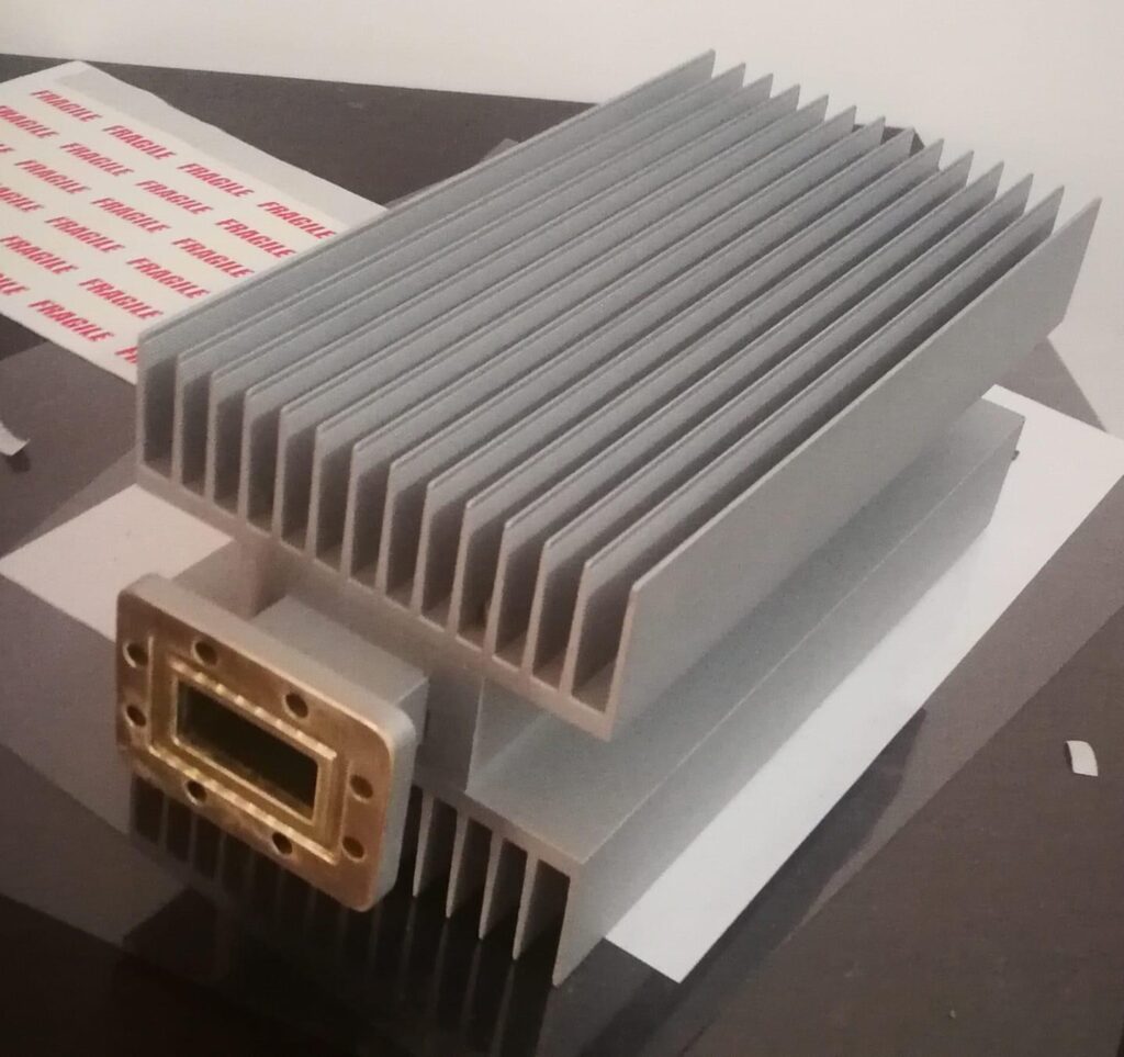
Low Noise Amplifiers (LNA’s)
LOW NOISE AMPLIFIERS-BROADBAND MMIC TECHNOLOGY Contain Input Signal Limiter PIN Diode Controlable Switch Alternate Connector and Flange Type Available Voltage Regulator Operating Temperature -50 To +60 Degrees C. Military Applications-Radars 4 Options of IN/Out Dimensions in MM
CISPR 16-1-1 standard
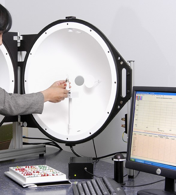
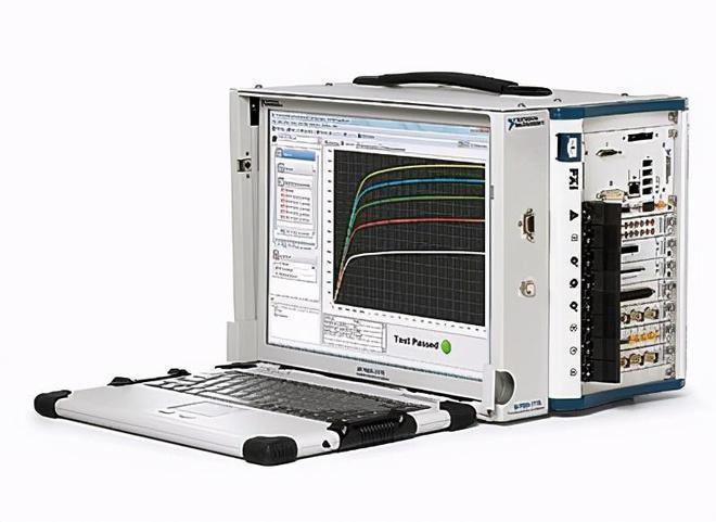
LED’S TEST SYSTEM
- Measure the optical, electrical parameters, characteristics of the radiating sources,different displays, lighting panels and LEDs.
- Highly automated measurements, analysis, temperature control and monitoring.
- Comparability with and external optical measuring devices (radiometers, spectrometers, etc.).
- Flexible hardware and software configuration.
CISPR 16-1-1 standard
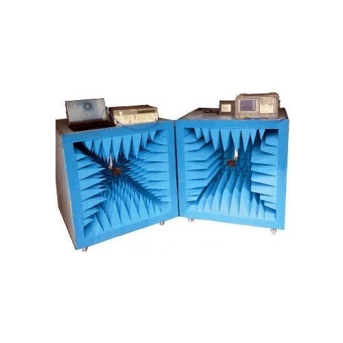
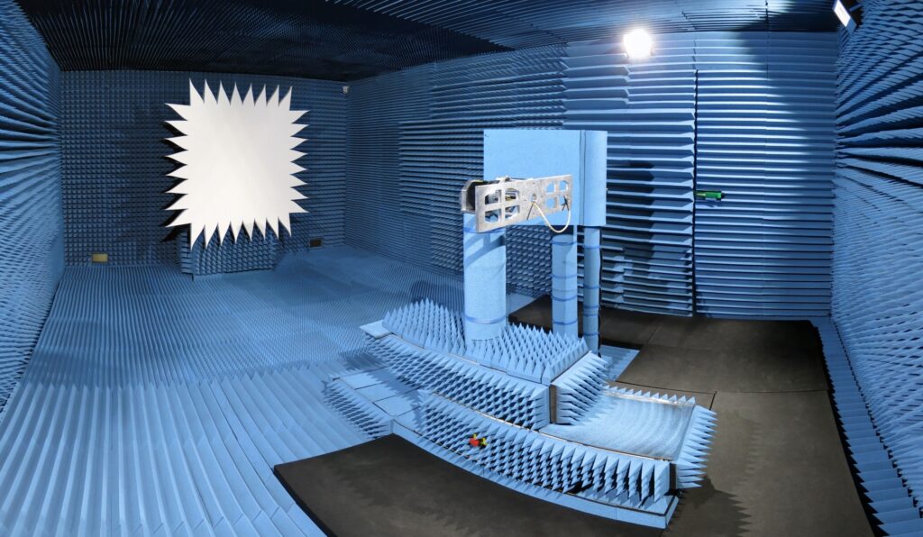
RF Portable Anechoic Boxes (made by JV Micronics)
Scientist and Engineers involved in Research and Testing of RF components like Antennas up to 40GHz, sometime needs small setup which may be easily portable and effective. Two detachable Anechoic Boxes are manufactured having pyramidal and wedge shaped RF absorbers on floor, roof and three walls leaving one side open. Two boxes with similar configuration are joined together with locking mechanism.
CISPR 16-1-1 standard
Compact Antenna Test Range
A Compact Antenna Test Range (CATR) is a type of range used for testing antenna systems at frequencies where obtaining Far-Field spacing to the AUT would be impractical using traditional free space methods. A CATR, based on a single reflector, uses a source antenna which radiates a spherical wave front, and one reflector to collimate the radiated spherical wave front into a planar wave front within the desired test zone. A CATR is used for microwave and millimetre wave frequencies where the 2D2 /λ far-field distance is large, such as with high-gain reflector antennas.
CISPR 16-1-1 standard
Waveguide Terminations
- High Power Terminations (Power rating till 3 KW )
- Medium Power Terminations (Power rating till 200 W)
- Low Power Terminations (Power rating till 50 W)
- Precision Power Terminations
CISPR 16-1-1 standard
PORTABLE EMC MEASUREMENT DEVICE
- Combined EMC Measurement and Test Devices, Ultra-wideband Spectrum
- Analyzer in a single package.
- Effective user interface.
CISPR 16-1-1 standard
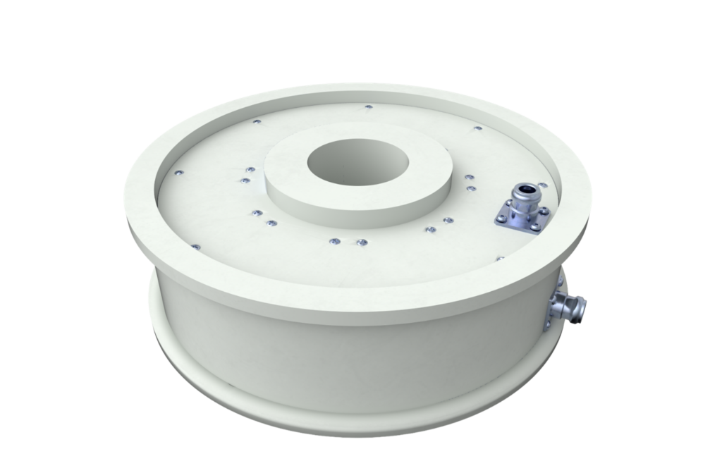
High frequency rotating transition
The high-frequency rotating transition is designed to transmit microwave signals in the 1030/1090 MHz frequency range from a fixed transceiver to a rotating radar antenna with minimal distortion.
CISPR 16-1-1 standard